

📸 Cameras 101 | Technology Series
📸 Cameras 101 | Technology Series
A simple guide to the fundamentals of cameras used in physical devices.

Hey Friends,
This is the first part of a series in which we outline common technologies used in building physical products.
I’ll be covering electromechanical disciplines such as cameras, displays, plastics, batteries, PCBs, soft goods, metals, sensing, and more.
This series isn’t meant to be a technical deep dive, rather it’s supposed to serve as a high level overview for product managers, engineers, designers, and enthusiasts.
Think of it like a refresher course for making more informed decisions when you want to implement these technologies in your next product architecture.
This post will be broken up into 3 sections:
Use cases & applications
How the technology works
How the technology is made
1. Use Cases
We’ll start by listing use cases as I am big proponent of highlighting customer experience and putting a context to the technologies we use.
Design/engineering shouldn’t be done in a vacuum. After all, the whole reason we make products is to (hopefully) solve user problems.
1.1 Self Driving
Teslas rely on a series of cameras and robust processing techniques to perceive a drivers surroundings for a variety of self driving experiences.
On the model 3 there are cameras mounted on the driver, passenger, front, and rear the vehicle. Note that the camera suite works in conjunction with ultrasonic and radar sensing to provide full self driving.


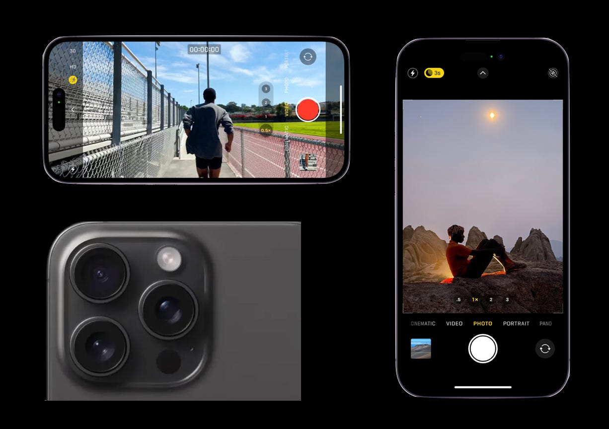
1.2 Photo/Video
Selfies, portrait mode, vlogs, and more. The most common use case of cameras is personal photography. In section 2 below we’ll discuss how iPhone cameras are made.
1.3 Mixed Reality
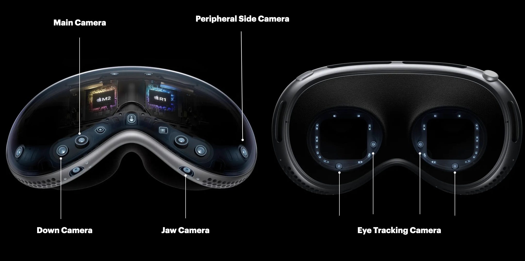
Cameras are used in the Apple Vision Pro to record real time video of the physical world to create a digital, mixed reality (augmented and virtual) experience via pass through.
To enable this experience there are:
2 main cameras for frontal environment capture
2 downward facing cameras for space and hand tracking (you can navigate device UI with your hands)
2 side cameras for peripheral capture and hand tracking
2 cameras for jaw capture
4 inward cameras to track your pupils (remember you can navigate with your eyes on the VP)
along with a sensing suite of IR illuminators and LiDAR.
1.4 Vision Systems
Vision systems are pieces of equipment in manufacturing facilities which use cameras as inputs and software processing to perform a variety of automated tasks such as issue detection, quality control, and robot guided assembly.

2. How Cameras Work
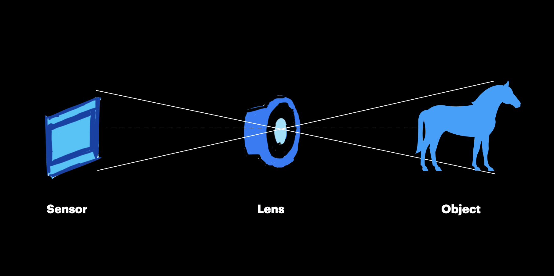
Summary: The lens concentrates incoming light from the object of interest via refraction to a sensor. This sensor then outputs a signal which is processed to create a digital image.
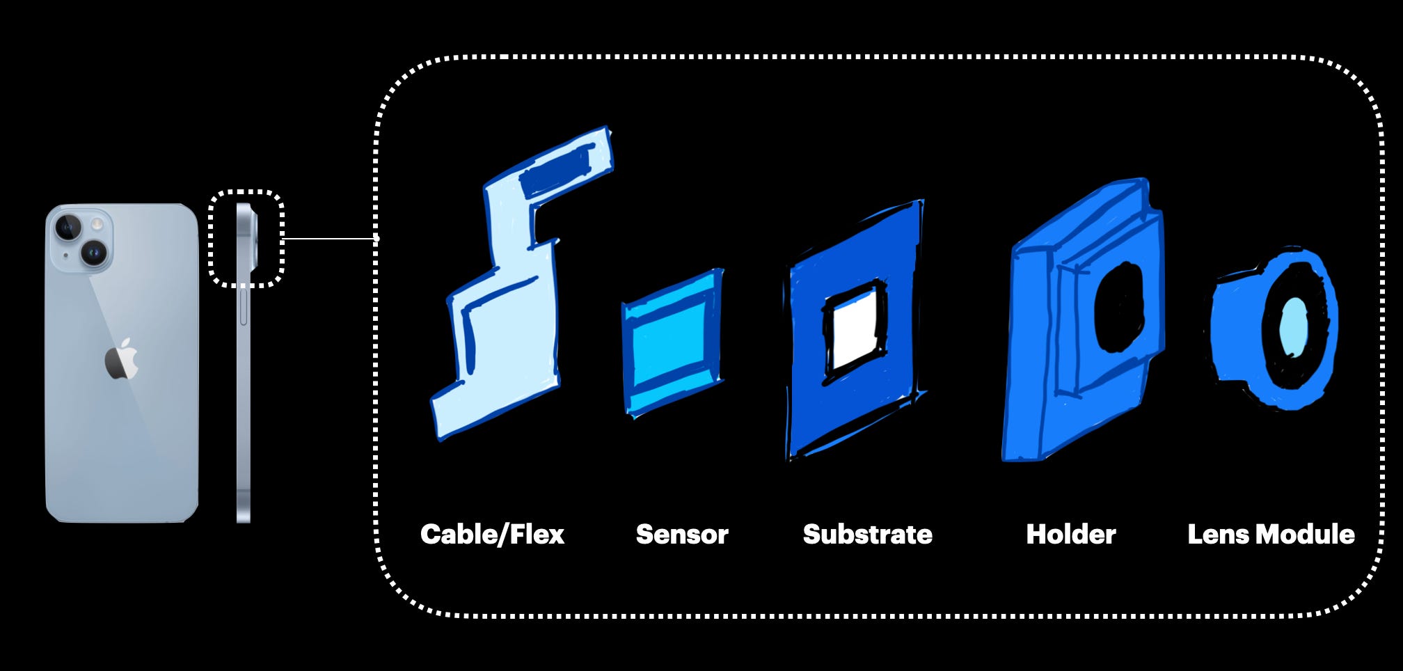
2.1 Key Components & Terms
Note that the parts listed below will focus on iPhones. While cameras for self driving, digital photography, and vision systems are different in architecture, they have similar fundamental components.
Lens
An optical device which directs light onto a sensor from the environment
Sensor
Transforms incoming light from the environment to an electrical signal
Sensors contain complex silicon with an array of photosites that collect light, thereby charging photons and then converting that charge to a voltage
The voltage signal is later processed via computational photography
Photosites also act as colour filters when overlayed
Substrate
Intermediary connection between sensor and flex
In some systems this is where the electromechanical actuators are attached for image stabilization
Flex
Electrical cable connecting the camera module to the system’s (phone in this case) main PCB for power and processing
IR Filter
Ensures that only wave lengths within the visible spectrum get to the sensor
Aperture
An opening which dictates amount of light to the sensor
Generally we want a larger aperture as it means we can work with more light, especially in dim conditions
One tradeoff is a shallower depth of field which reduces focus
Depth of Field
Portion of distance for which objects are in focus
Higher depth of field = entire image (background to foreground) is in focus
Lower depth of field = objects in foreground are sharp and background is blurry
Focal Length
How effectively an optical system converges or diverges light
Shorter focal lengths result in larger field of views and smaller magnification
Field of View
The width of what you can capture, a function of sensor size and focal length
Field of view increases with lower magnification
Megapixel
Used for resolution, is the number of pixels on a camera’s sensor
For example 16 MP = 16 million pixels on the sensor layout
Stabilization
Stabilization helps prevent movement to take better photos. There are generally 2 types:
Sensor Stabilization
When the sensor moves via an array of micro mechanical actuators and electromagnets (usually in 2 dimensions except for iPhone 15 where it’s in 3D)
This is also sometimes paired with the lens moving aswell in the optical axis for zoom and focus
Electrical Stabilization
This is where exposures and frames are adjusted instead of hardware
3. How Cameras Are Made
Smartphone cameras need to be manufactured in cleanrooms which are controlled environments that filter for foreign contaminants.
3.1 Manufacturing
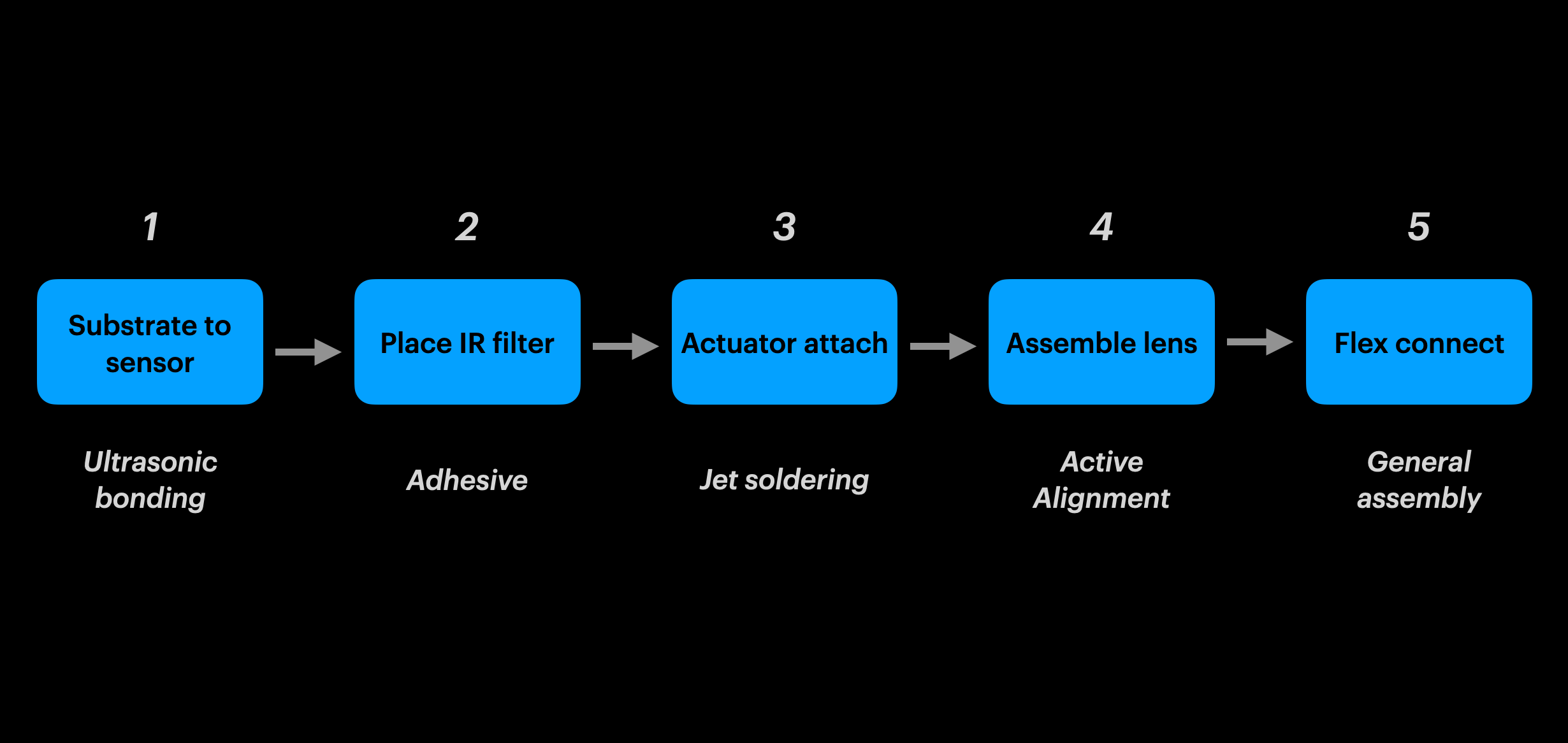
The steps below are for final assembly, assuming all sub components (such as the lens module, sensor, flex, etc) have been pre assembled at sub suppliers.
Step 1
Ultrasonic bonding is used to create a connection between the substrate and sensor
Step 2
The IR filter is assembled to the substrate via adhesive
Step 3
Jet soldering is used to create an electrical connection between the substrate assembly and electromechanical actuator assembly
Step 4
This is the most critical step to maintain image precision, quality, and focus
Active alignment machines move and position (transverse, tilt, rotation) both the lens and sensor relative to each other to find the best location for optimal image quality
Once that’s done the final bond is performed via adhesive
Step 5
The flex is attached to the lens/substrate/sensor assembly
3.2 Manufacturing Challenges
A. Particles
Particles result in defective photos for the end user
They create poor contrast, defective light characteristics, and blemishes when embedded onto the lens or sensor

Based on the camera module’s design requirements, some manufacturing facilities may be required to control particles to the size of ~25 microns
For reference, the human red blood cell is ~ 8 microns and a human hair is ~80 microns

Imagine the difficulty in controlling processes to that level of granularity in a mass production, high volume, fast paced factory - its important to consider this for non technical PMs as these factors impact throughput, yield, scheduling and volume targets
Particles are usually caused by dust, hair, adhesives, machines, grease and a variety of environmental, process, and human factors
Mitigations include automated assembly to minimize handling, clean rooms, air filtration, operator gowning processes, and strict cleaning SOPs
B. Flare
Images with foreign substances which are not present in the environment when the user is taking a photo.
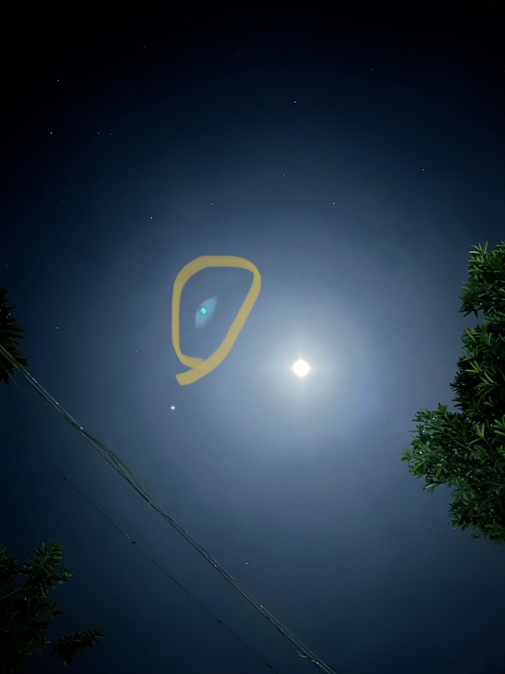
Flare can be caused by improper relative positioning of components in the mechanical assembly (adhesives, lens, sensor) or contaminants. This can allow for reflections which let unintended photons reach the sensor. This results in the distortions like the one shown above.
And thats all for now.
If you enjoyed this article feel free to suggest what other technologies you would like an overview of.
Also spread the word and subscribe!
Thanks for compiling, very informative !